433MHz RF Transmitter and Receiver (YK04) – Wireless LED Control Project Explained
By Vidumina STEM Zone | Beginner Electronics Projects
What If You Could Control a Light Without Touching It?
Imagine pressing a button on a small remote and watching a light turn on — no wires connecting them, no Wi-Fi needed, no smartphone involved. Just a simple radio signal doing the work. Sounds cool, right?
That's exactly what this project is about. Using a 433MHz RF transmitter and receiver module (YK04), you can send wireless signals from a small handheld remote to a receiver circuit, and use those signals to control outputs — like LEDs, relays, or buzzers.
In this article, we'll walk you through a real working project where two LEDs are controlled wirelessly using the YK04 RF module. We'll explain every part of the circuit step by step, matching the explanation with real project photos. Whether you're a complete beginner or an Arduino learner exploring wireless communication, this project is a great place to start.
Components Used in This Project
Here's everything we used to build this wireless LED control project:
- YK04 433MHz RF Transmitter and Receiver Module (4-channel)
- Breadboard (standard 830-point)
- Breadboard Power Supply Module (3.3V / 5V)
- Jumper Wires
- 2 × LEDs (any color)
- 2 × 220Ω Resistors (to protect the LEDs)
- 9V Battery or DC Power Adapter (for power supply module)

The best part? All of these are cheap and easy to find online or at any local electronics shop. The YK04 module set — transmitter and receiver together — usually costs less than a dollar or two.
Project Overview
The idea is simple. The YK04 RF transmitter is a small handheld remote with four buttons labeled A, B, C, and D. When you press a button, it sends a coded radio signal at 433MHz frequency.
On the other side, the RF receiver module picks up that signal and activates the matching output channel. In this project, we connected LEDs to two of those output channels (channels A and B). So when you press button A, LED 1 turns ON. Press button B, and LED 2 lights up.
No Arduino. No programming. No internet. Just pure hardware communication.
Our project photos will show you:
- The YK04 transmitter and receiver modules up close
- The breadboard wiring setup
- The complete assembled circuit
- The LEDs lighting up during a live test
Understanding 433MHz RF Communication (Simple Theory)
Before jumping into the circuit, let's quickly understand what's happening behind the scenes — in plain English.
RF stands for Radio Frequency. It's a way of sending information wirelessly through the air using radio waves — similar to how your TV remote or garage door opener works. The 433MHz refers to the frequency of the radio wave being used, which is 433 megahertz. This is a license-free frequency band available in most countries, which is why it's so popular in hobbyist electronics.
YK04 Receiver Output Behavior
The YK04 receiver outputs are digital signals, meaning each channel behaves like a simple ON/OFF switch. When a button is pressed, the corresponding output pin goes HIGH (approximately 5V), and when turned off, it returns to LOW (0V).
Each output pin can typically supply only a small amount of current (usually less than 10–20mA). This is enough for LEDs but not enough to drive high-power devices directly. For controlling larger loads such as bulbs or motors, a relay module or transistor driver circuit must be used.
Here's how it works in our project:
- When you press a button on the transmitter, it generates a short burst of 433MHz radio waves, encoded with a specific pattern for that button.
- The receiver module is constantly listening on 433MHz. When it detects the right signal pattern, it activates the corresponding output pin — pulling it HIGH (usually 5V).
- That HIGH signal can then power an LED, trigger a relay, or do anything else you connect to it.
Key things to know:
- No internet or Wi-Fi is needed
- The typical range is 20 to 100 meters in open space (walls and obstacles reduce this)
- It's a one-way communication — the transmitter sends, the receiver listens
Photo 1: The YK04 Transmitter and Receiver

The YK04 transmitter looks like a small keychain remote. It has four buttons — A, B, C, and D — each mapped to a specific output channel on the receiver. It runs on a small 12V battery (usually a coin or A23 battery included in the kit).
The receiver module is a small PCB board with clearly labeled pins:
- VCC – Power input (5V)
- GND – Ground
- D0, D1, D2, D3 – Output channels corresponding to buttons A, B, C, D
Each output pin goes HIGH when the matching button signal is received. Depending on the receiver's configured mode (momentary or latching), the output may stay HIGH or return LOW after release.
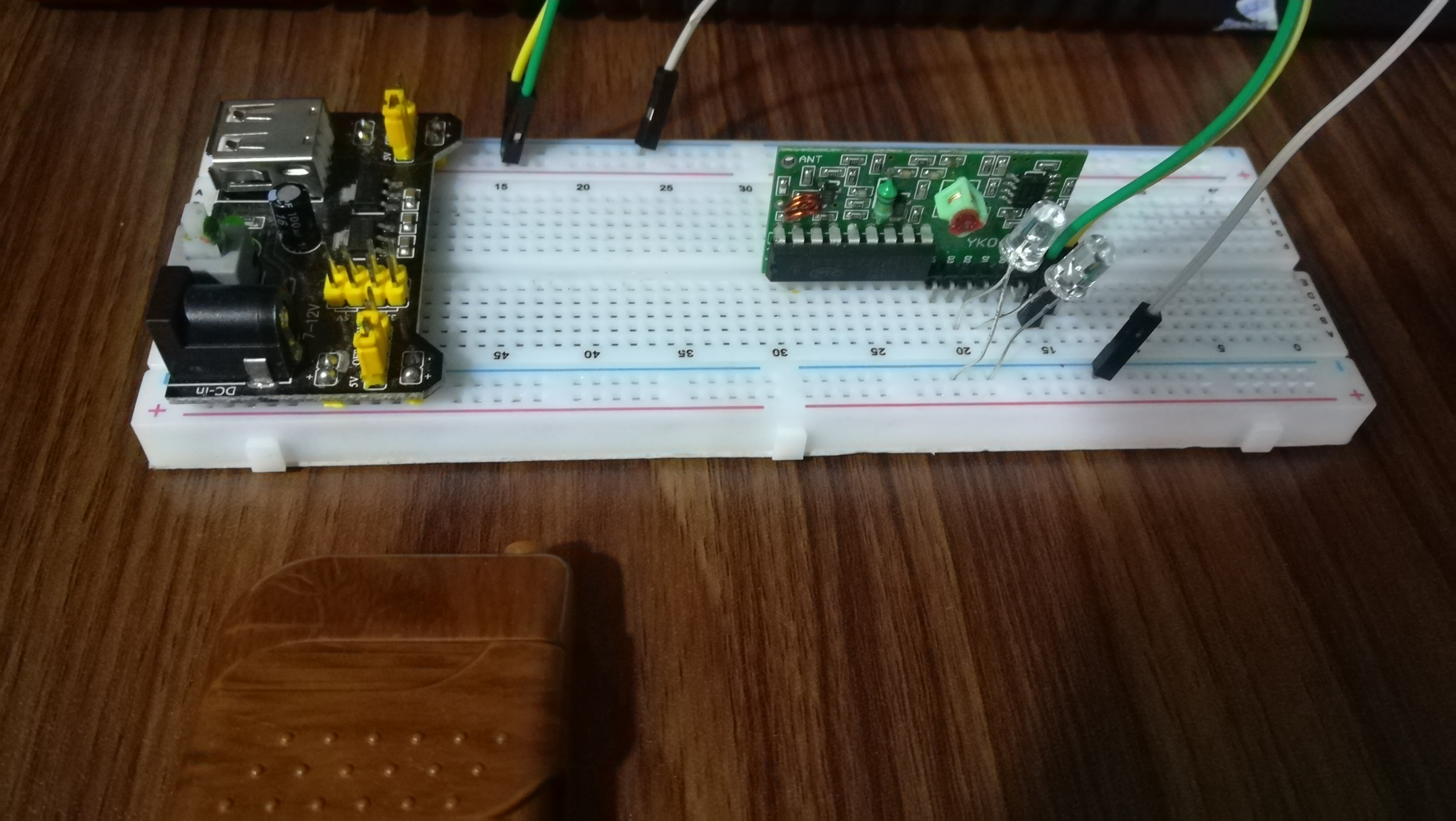
Photo 2 & 3: Breadboard Circuit Setup


Let's build the circuit. Here's the step-by-step setup:
Step 1 – Power the Breadboard Plug the breadboard power supply module into the top of your breadboard. Connect your 9V battery or DC adapter. Set the output to 5V using the jumper on the module. This powers the entire circuit.
Step 2 – Place the RF Receiver Module Place the YK04 receiver on the breadboard. Connect:
- VCC pin → 5V rail on the breadboard
- GND pin → GND rail on the breadboard
Step 3 – Connect the LEDs Use jumper wires to connect the receiver's output pins to your LEDs:
- D0 (Channel A) → 220Ω resistor → LED 1 anode (+)
- D1 (Channel B) → 220Ω resistor → LED 2 anode (+)
- Both LED cathodes (−) connect to the GND rail
The resistors are important — without them, too much current flows through the LED and it can burn out. Always use a current-limiting resistor with LEDs.
Step 4 – Double Check Make sure all jumper wires are seated firmly in the breadboard holes. Loose connections are the number one reason beginner circuits don't work.
YK04 Receiver Pin Summary
VCC – Connect to 5V power supply
GND – Ground connection
D0 – Output for Button A
D1 – Output for Button B
D2 – Output for Button C
D3 – Output for Button D
Photo 4: How It Works in Action

This is the fun part! Once power is turned on and the circuit is assembled, here's what happens:
-
Press Button A on the YK04 remote → The transmitter sends a 433MHz signal coded for Channel A → The receiver detects it → D0 pin goes HIGH → Current flows through LED 1 → LED 1 turns ON ✅
-
Press Button B → The transmitter sends Channel B signal → D1 goes HIGH → LED 2 turns ON ✅
-
Press the same button again → The output toggles back → LED turns OFF
The YK04 works in latching mode by default — meaning the output stays ON after one press and turns OFF after the next press. This makes it behave like a real light switch, which is very satisfying to use.
Real-Life Applications of 433MHz RF Modules
This little wireless LED demo is just the beginning. Here's what you can actually build with 433MHz RF modules:
- Wireless room light control – Replace LEDs with relay modules to switch actual mains lights
- DIY doorbell system – Press a button at the door, a buzzer rings inside
- Remote power switch – Turn on/off fans, pumps, or garden lights wirelessly
- Simple home automation – Control multiple appliances from one remote
- Wireless alarm trigger – Press a button, activate a buzzer or siren remotely
Can You Use This with Arduino?
Yes — the output pins of the YK04 receiver can be directly connected to Arduino digital input pins.
Instead of controlling LEDs directly, you can read the receiver signals in code using digitalRead() and trigger more advanced logic such as:
- Timers
- Automation sequences
- IoT integration
- Data logging
This turns a simple RF remote into a smart wireless control system.
"What is Arduino? Complete Beginner Guide"
Arduino UNO pin diagram explained
Advantages and Limitations
Advantages:
- Very low cost — the whole module set costs less than most coffees
- No programming required — just wire it up and it works
- Easy to use — perfect for beginners
- No internet or router needed
- Works over a decent range in open areas
Limitations:
- Limited range — obstacles like walls reduce the effective distance significantly
- No encryption or security — any YK04 transmitter nearby could trigger your receiver
- Susceptible to interference — other 433MHz devices in the area can cause false triggers
- One-way communication only — the transmitter doesn't know if the receiver got the signal
Common Beginner Mistakes to Avoid
If your circuit doesn't work the first time, check these common issues:
- Reversed power connections — Always double-check VCC and GND before powering on. Reversing polarity can damage the module instantly.
- Loose jumper wires — On a breadboard, wires can look connected but aren't. Press each one firmly.
- Missing resistors on LEDs — LEDs without current-limiting resistors will burn out quickly.
- Wrong transmitter/receiver pair — The YK04 transmitter and receiver are sold as a matched pair. Using a generic 433MHz module from another brand may not work without re-pairing.
- Expecting long range indoors — Don't expect 100 meters through walls. Real indoor range is often 10–30 meters.
- Forgetting to power the receiver — It seems obvious, but always check the VCC and GND connections first.
Conclusion: Your Turn to Build It!
The 433MHz RF transmitter and receiver (YK04) project is one of the most satisfying beginner electronics builds out there. You get to see real wireless communication in action — no coding, no complex wiring, just radio waves doing their job.
Once you've got the two LEDs working, the logical next step is to replace the LEDs with relay modules. That lets you control real-world appliances — lights, fans, pumps — safely. You can also explore connecting the RF receiver output to an Arduino to add smarter logic, timers, or even triggers for more complex projects.
Start simple, understand how each part works, and then expand. That's the Vidumina STEM Zone way.
Try this project at home, share your results, and let us know how it went in the comments below!
Tags: 433MHz RF transmitter receiver, YK04 RF module, wireless LED control project, RF remote control circuit, beginner electronics, Arduino wireless project

Comments (1)
Leave a Comment